Design of shear walls with openings on seismic response using E-Tabs ie. 9 storey steel structure of 20 000 m2 floor area supported on inclined columns.

Structure Magazine Efficient Design Of Steel Plate Shear Walls
The most convenient place to locate shear wall is an external blank wall on edges or on two parallel edges so that stiffness of structure is maintained in best possible way.

Concrete shear wall design example steel frame building. A shallow construction depth of 310 mm was achieved using Slimdek for a structural grid of approximately 7 m. This report gives a detailed explanation of how stand pro can be effectively used to design shear walls. H 15 ft.
ACI 318-05 Design data. Building WeightSPSW result in a lesser building weight in comparison to buildings that use concrete shear walls. Shear walls are constructed to counter the.
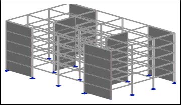
V 3 50 kips. The example building consists of the main block and a service block connected by expansion joint and is therefore structurally separated Figure 1. The building model is as shown in the Fig1 having 8 bays in the X and 6 bays in the Y directions with a bay width of 6m and 5m.
It is interesting to compare this example with Table I in the Arup paper. A concrete shear wall core and c. Typical Steel Plate Shear Wall Plastic Analysis of SPSW Using the collapse mechanism of a single story SPSW in a frame with simple connections represented by the strip model as shown in Figure 4 results in the following equation for base shear Berman and Bruneau 2003b.
Horizontal reinforcement W17 16 in. The flanges of the shear walls have been ignored as in T-beams in building frames because the horizontal loads are generally of a reversible nature. According to the limiting condition I in this table the main shear walls in a 200 ft high building 40 ft wide should support at least one eighth of the total weight of the building.
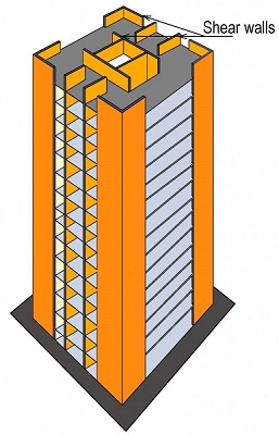
Shear forces can also be resisted by steel braced frames which can be very effective at resolving lateral forces but may be more expensive. Of movement joints maximum spacing 10 ft. Thin walled hollow RC shafts around the elevator core of the buildings also acts as shear walls and should be taken advantage to resist earthquake forces.
Analysis and design for main block is to be performed. Of openings within 8 in. SHEAR WALLS Shear walls are vertical elements of the horizontal force resisting system.
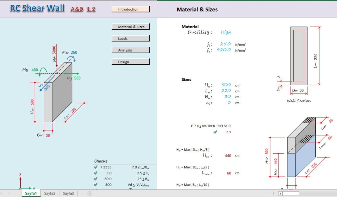
This resulted in a savings of approximately 2 in gross square footage. Reinforced Concrete Shear Wall Analysis and Design A structural reinforced concrete shear wall in a 5-story building provides lateral and gravity load resistance for the applied load as shown in the figure below. Shear wall section and assumed reinforcement is investigated after analysis to verify suitability for the applied loads.
In Steel building design. V 2 25 kips. L w 18 ft.
The above philosophy may be applied to any shape and size of shear wall layout in a building. Tolworth is 22 storeys 48 ft wide and the shear walls support one ninth of the building. A s Area of reinforcing steel mm 2.
Or 4 in bond beams 10 ft A B Ordinary Reinforced. Design Example 3 Cold-formed Steel Light-frame Three-story Structure Foreword The building in this example has cold-formed light-gage steel framing and shear walls and diaphragms that are sheathed with wood structural panels. A nine-story wing borders the adjacent One Van Ness building to the north and a two-story wing is planned to border 11th Street to the east.
To a concrete shear wall thickness with an average of 28 refer to Figure 2. The thickness and the length of the walls are determined as per the design requirements. It should be spaced symetrically so that center of gravity cg of structure remains at center and there is not much eccentricity on application of lateral loads.
Extended three dimensional analysis of building. Specific rules for the design and detailing of steel buildings. H 10 in.
Typically shear walls are constructed as lift core walls and around the staircases. L and U shaped sections are also used. Design of reinforced concrete non-load bearing shear wall.
What is the Difference between Column and Shear Wall. Infill walls of thickness 250mm are located in the outer frames in each floor with the ground floor. This is because past and present design.
Shear walls are oblong in cross section that is one dimension of the cross section is much longer than the other while rectangular cross section is common. 2 The building will be used for exhibitions as an art gallery or show room etc so that there are no walls inside the building. Shear walls are particularly important in large or high-rise buildings or buildings in areas of high wind and seismic activity.
The building is a residential building having G10 floors with 35m storey height. Design examples Example 1. The office tower is a 16-story steel framed structure with concrete on metal deck also with two podium wings.
The nose of the building provides an auditorium and cantilevers 26 m from the adjoining structure. Use of Shear Wall. Shear walls are typically constructed from materials such as concrete or masonry.
The stiffness of walls lying parallel to the direction of loading may only be included in the computation. A s Area of compression reinforcing steel in a spandrel mm 2. A sc Area of reinforcing steel required for compression in a pier edge member or the required area of tension steel required to balance.
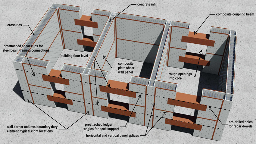
Design of Reinforced Concrete load bearing shear wall. 189 518 Definition of the structure. Many of those systems involve use of a composite floor slab concrete acting compositely with profiled steel sheeting and most use steel beams acting compositely with the floor slab.
V 4 75 kips 3rd floor. This example presents a new approach to the seismic design of this type of building. 189 iii Composite steel concrete frame with eccentric and concentric bracings.
Slimdek consists of asymmetric steel beams ASB support a deep. V r 100 kips. Medium rise braced frames P3651 general guidance is given on a range of floor systems suitable for steel framed buildings.
Minimum required area of distributed horizontal reinforcing steel required for shear in a wall spandrel mm 2 mm. The shear wall is a concrete wall constructed from the foundation level to the top of the building. Shear walls which are used in buildings to carry forces.
Shear Wall Types 12 Shear Wall Type Minimum Reinforcement Seismic Design Category Ordinary Plain none A B Detailed Plain vertical reinforcement 02 in2 at corners within 16 in. A study performed for The Century project indicated that the total weight of the.

What Is Shear Wall Why And Where It Is Provided Civil Snapshot

Composite Building Systems Resisting System Northern Architecture

Typical View Of Sprc Shear Wall In Construction Site Of Shanghai Tower Download Scientific Diagram
An Analytical Study About The Use Of Steel Plate Shear Walls To Improve Lateral Rigidity Of Reinforced Concrete Framed Structures


Tall Building Design

Integrating Concrete Masonry Walls With Metal Building Systems Ncma
Shear Walls Civil Engineering Forum
Shear Walls Types Of Shear Wall And Its Efficiency

Shear Wall Functions Loads Transfer Mechanism Design Example Of Shear Wall Civildigital
What Are Shear Walls Quora
Rc Shear Wall Analysis And Design Spreadsheet
Shear Wall And Core System In Tall Buildings
Ce Center
Ce Center

Rc Shear Wall Plan Google Search How To Plan Concrete Building Structures
Shear Wall Designing Buildings Wiki

Pdf Seismic Design Guidelines For Solid And Perforated Hybrid Precast Concrete Shear Walls

Tall Building Design

Composite Building Systems Resisting System Northern Architecture
Komentar
Posting Komentar